
Electromagnetic Clutch and Brake Control Circuit Design Considerations
Release Date:09/10/2019
If the electromagnetic clutch and brake on your equipment are in use, the current voltage or control circuit is abnormal, and the electromagnetic clutch and brake are unstable, which may cause the production to not work properly. Please see the following introduction. If it is not resolved, please refer to:
Since the electromagnetic clutch and brake have an electromagnetic coil inside, it is necessary to use the relay under the DC induction load condition of the relay used. This is because the surge voltage generated by the electromagnetic clutch and the brake during control will greatly consume the contacts. If the protection circuit can be designed on the electromagnetic clutch and brake, the control contacts will also be protected.
If the electromagnetic clutch and brake control are performed on the AC side, the time of the armature release will be delayed, so that high-frequency operation cannot be achieved. Therefore, the control contact should be placed on the DC side and the supply voltage of the electromagnetic clutch brake. When designing the power supply circuit, the variation of the excitation voltage should be suppressed within ±10% of the rated voltage of the electromagnetic clutch brake. The above is the introduction of the control circuit configuration and precautions for the electromagnetic clutch and brake, and can be understood from other aspects.
High quality electromagnetic clutch and brake consultation:

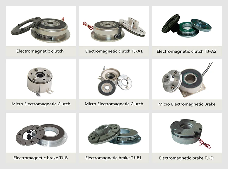
Click On Electromagnetic clutch and brake product:
http://www.tianjidg.com/list_35.html
http://www.tianjidg.com/list_34.html


 Leave Messages